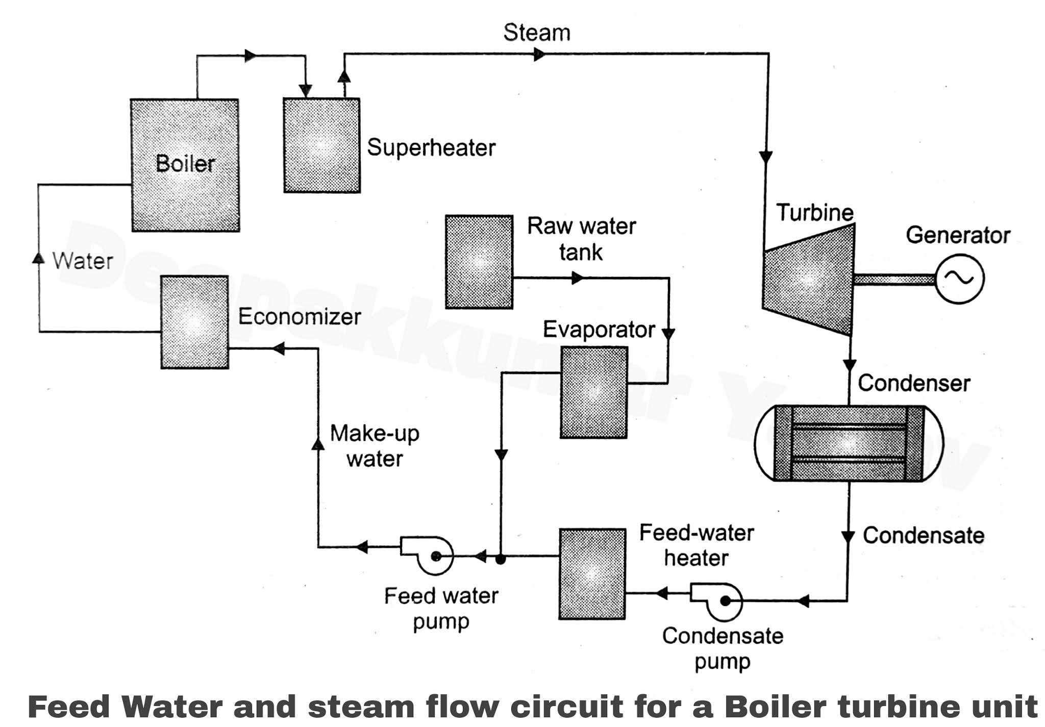
Cooling Water Circuit Diagram Cooling Engines
Circuit diagram of water flow sensor namely yf-s401. System water cooling diagram cav burnett jonathan courtesy sfo Generator freshwater diagram water line fresh cooling jacket detail operation temperature engine seawater type evaporation low ship marine tube board
Hot Water Central Heating Systems Diagrams
Cooling circuit Water air cooler circuit diagram Disinfectant monitoring in a cooling water circuit
Flow diagrams
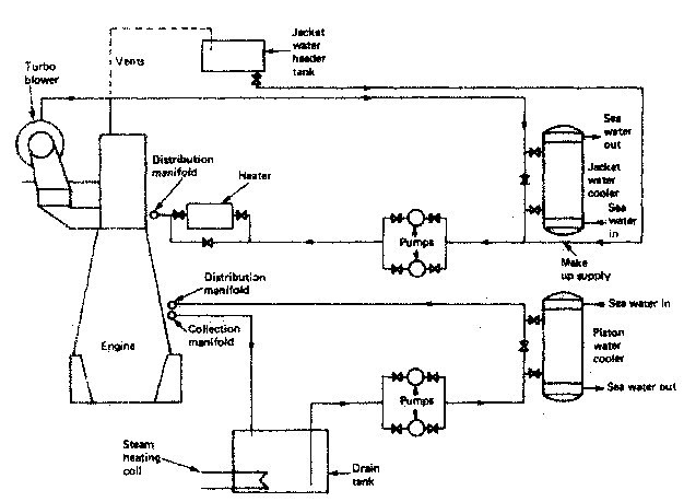
Few drawings for easy understanding:05-06-06 water cooling system Figure a.14: fresh water cooling system diagramAdvanced cooling water treatment concepts (part 6).
Solved: calculate the surface areas of the fresh water and lubricatingWater cooling: raw water cooling system 3 1l engine cooling system diagramWater cooled chillers -leading industrial chiller manufacturer丨senho.
Cooling tower piping diagram
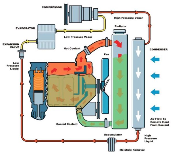
Hot water central heating systems diagramsTypical water cooling circuit flow diagram Coolant car water concentration diagram system cycle cooling radiator engine antifreeze auto through calculate fluid cool process mixture do notSchematic of the condensing water loop of a water-cooled chiller.
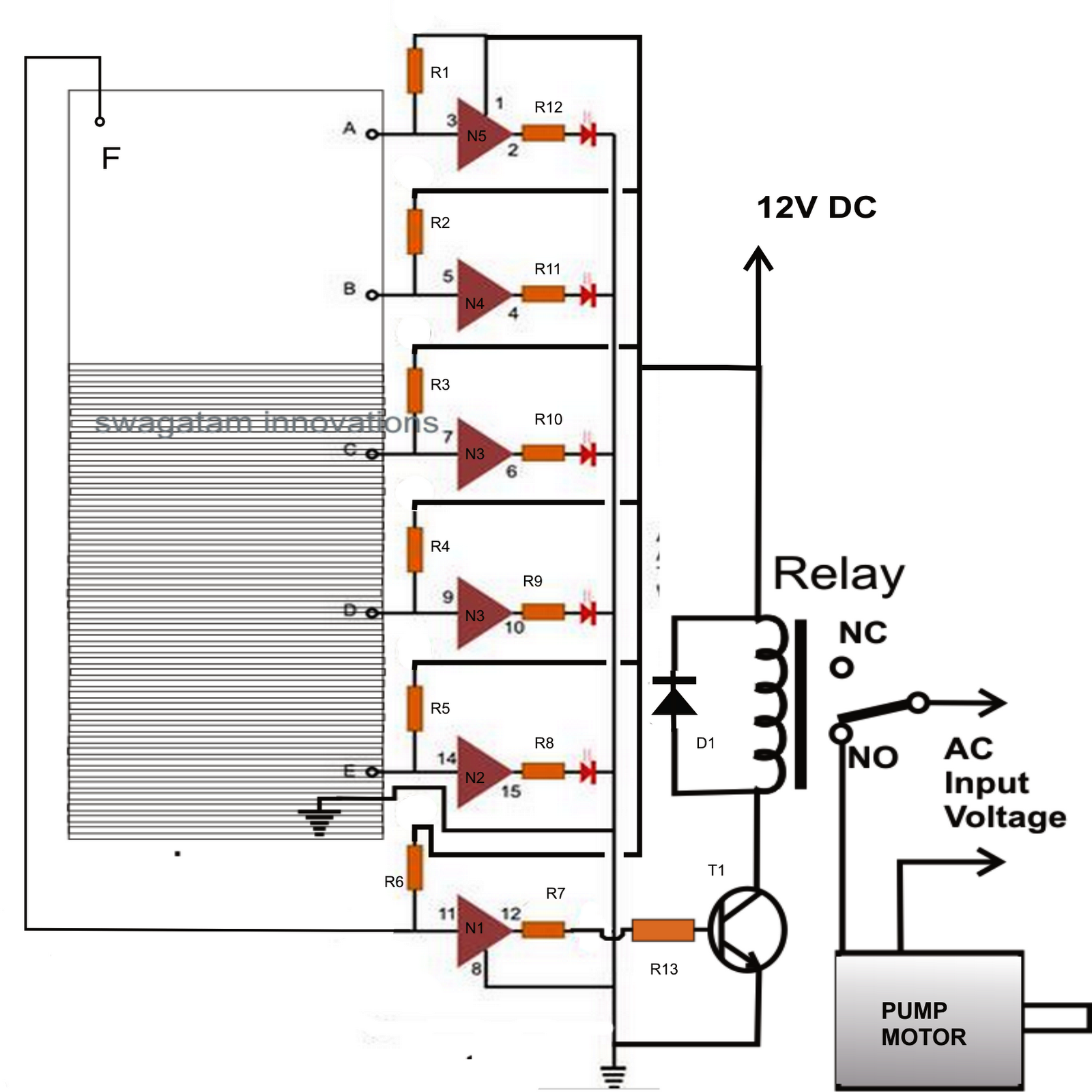
Simple water level indicator using transistorsCooling system water fresh engine diesel marine jacket sea speed slow systems stroke large two drawings works turbo cylinder piston Radiator flow flushing heating amana flush e90 conditioning coolant fluid mechanic vixion rover chevy sistemSchematic diagram of the cooling water circuit..

Indicator transistors electrosome leds indicate
Cooling system/piping helpJacket water cooling system of main engine marine diesel engine Simple water level indicator circuitFlushing the cooling system.
Cooling circuit diagram of a carChiller water cooled industrial temperature chillers working principle low standard glycol senho specifications details Water cooler schematic diagramProcess water solutions for wastewater.
How to calculate the concentration of coolant in a car
Cooling enginesCooling water circuit diagram Level water circuit indicator diagram make electronic projects ic given belowFreshwater generator archives.
Diagram flow mercruiser cooling system closed engine water boat loop v8 marine perfprotech diagrams fwc systems 10th monday february investigationChiller cooled condensing chillers coolant Liquid level indicator circuit diagramCooling water system of the marine engine.
Cooling water circuit diagram
Scheme of the component cooling water system.Cooling coolant suzuki system parts flow hose runs vitara sidekick engine geo help Cooling towerMake this water level indicator circuit at home.
Cooling water circuit diagram .


Advanced cooling water treatment concepts (Part 6)

Schematic diagram of the cooling water circuit. | Download Scientific

Hot Water Central Heating Systems Diagrams
Flushing the Cooling System | Gearhead Test Garage

Cooling Water Circuit Diagram

Scheme of the component cooling water system. | Download Scientific Diagram

Process Water Solutions for Wastewater | CircleH2O